


Solar Street Lights in Southeast Asia Rainy Season: Common Challenges and Reliable Solutions
Solar street lights in Southeast Asia often face challenges during the rainy season. Learn common problems and practical design solutions for reliable performance.

Solar Street Lights: Benefits, Applications and How to Choose the Right System
Solar street lights are becoming an increasingly popular lighting solution for urban and rural infrastructure projects. This guide explains how solar street lights work, their main benefits, common applications, and the key factors to consider when selecting a reliable solar lighting system.

Is Solar Street Lighting Reliable for Road Projects? A Practical Engineering Guide
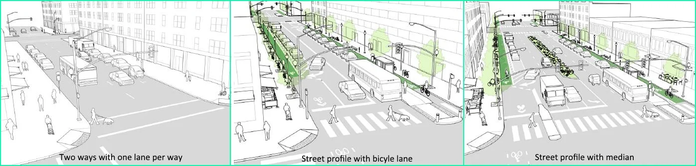
Solar street lighting is increasingly used in road projects, but reliability depends on proper system design and project conditions. This article explains the key factors that determine long-term performance, including solar system configuration, battery strategy, lighting design, and real road parameters.
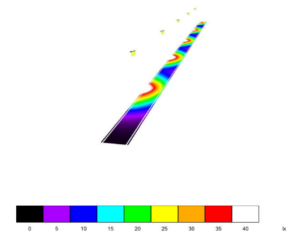
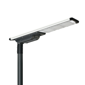
How to Design a Reliable Solar Street Lighting System?
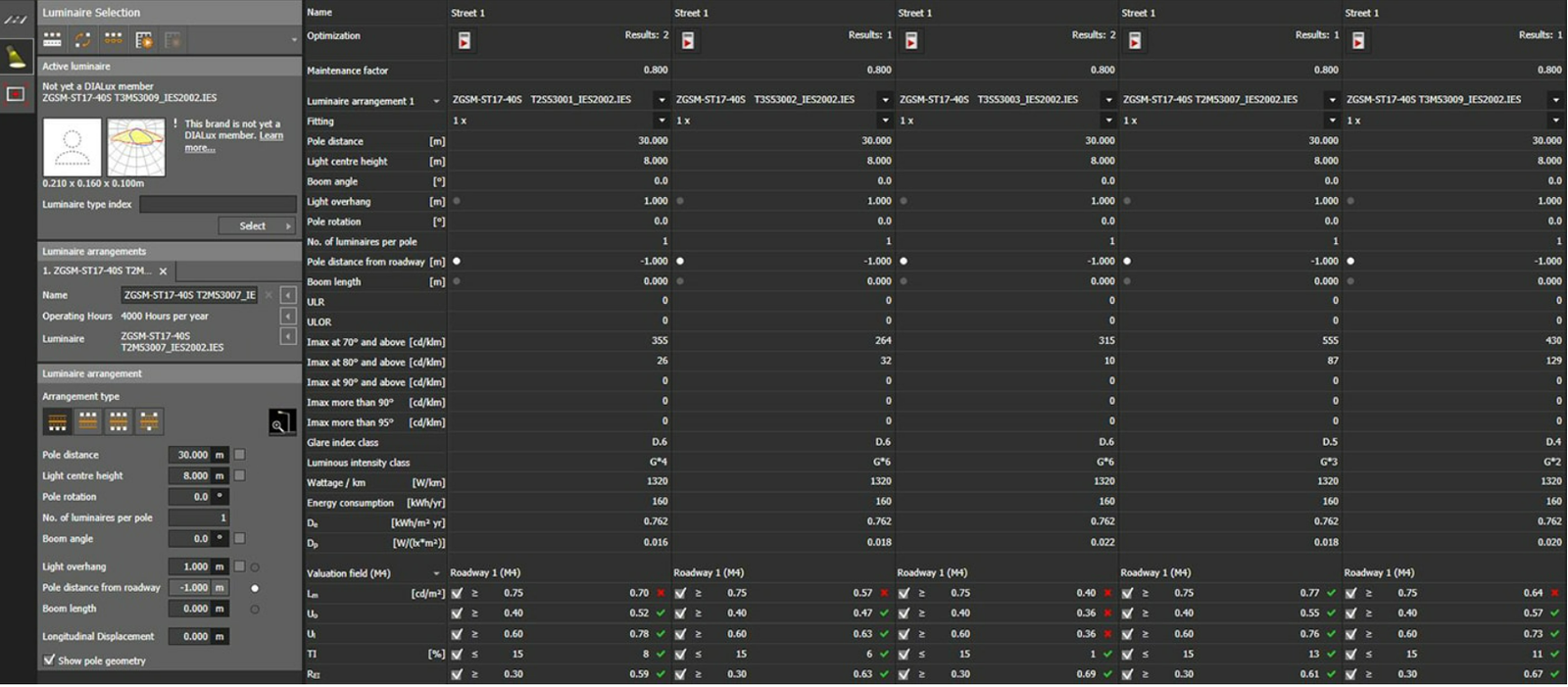
Learn the key factors that determine solar street lighting performance, including road width, pole height, spacing, climate conditions, and backup days. A practical guide for planning reliable solar street lighting projects.

OEM/ODM/SKD
Why Choose Aimlux? OEM/ODM/SKD Aimlux was founded by a diverse team comprising experienced and energetic members with a cumulative industry experience that caters well to
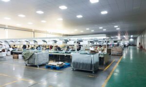
Reliable Road Lighting Manufacturer
Explore Aimlux’s street light manufacturing capabilities, from mold design to final testing, with full in-house production, strict quality control, and global project experience.

Serious Quality Control
Explore Aimlux’s complete quality control system, ensuring every LED road lighting product is tested, inspected, and fully traceable before delivery.

Global Quality Standard
Global Quality Standard Our factory is ISO9001 and ISO14001 certified, offering OEM/ODM/SKD services. With a professional production and QC team, we ensure high-quality products at
